
Street Fighter One, the groundbreaking precursor to the global phenomenon Street Fighter II, holds a unique place in gaming history. Beyond its revolutionary gameplay for the time, the original arcade release boasted a distinctive feature: a pneumatic cabinet. This technical deep dive explores the intricacies of the Street Fighter One pneumatic system, offering a reference for enthusiasts and those curious about this fascinating piece of arcade history.
The Dichotomy of Street Fighter One Cabinets: Deluxe and Standard
When Street Fighter One debuted in arcades, it wasn’t in a single, unified form. Two distinct cabinet types emerged in the US market: the Deluxe, famously known for its pneumatic controls, and the Standard, which adopted a more conventional six-button layout. Interestingly, interviews with the original developers at Polygon reveal that the Standard version was conceived after the Deluxe cabinet struggled to gain traction in the market. This suggests that the six-button iteration was a more cost-effective and player-friendly response to the initial lukewarm reception of the pneumatic system.
The Standard cabinet for Street Fighter One was housed within the widely used Dynamo HS-1 cabinet. This cabinet was a workhorse for Capcom in the 1980s, providing a familiar and reliable enclosure for many of their dedicated arcade releases. A key characteristic of the Standard SF1 cabinet was its button configuration. The attack strength was mapped to the six buttons in a left-to-right decreasing order. This layout, however, was reversed in its iconic sequel, Street Fighter II, a testament to the iterative design process in game development.
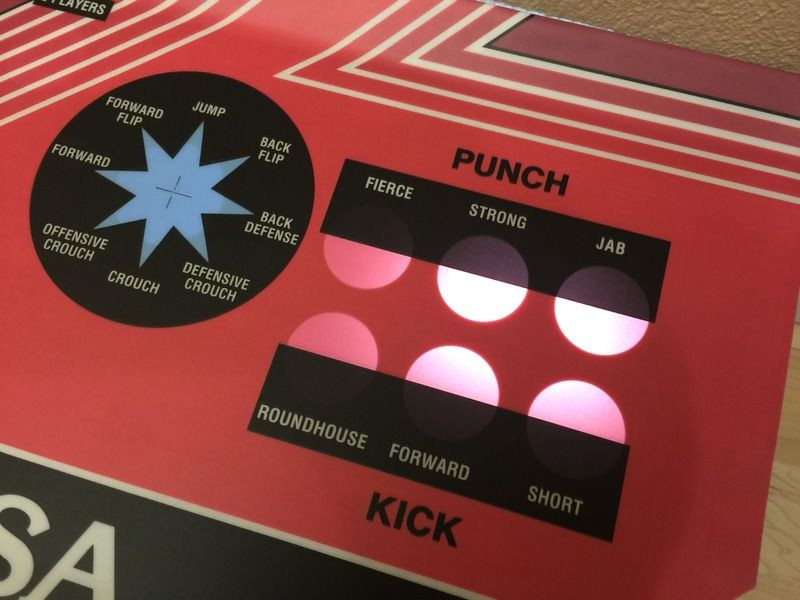 Street Fighter One Standard Control Panel Overlay, showcasing the six-button layout.
Street Fighter One Standard CPO reproduced by Biomech011, illustrating the classic six-button configuration.
Adding another layer of complexity to the cabinet variations is the possibility of a cocktail version of Street Fighter One. According to a report in Game Machine’s Upright / Cockpit Videos list from October 1987, a “cheaper cocktail table version” topped the Table Videos list in January 1988. While intriguing, it remains unclear whether this refers to US or worldwide sales, or even a Japanese-specific release. Advertisements from Japan do depict both Deluxe and Cocktail versions of SF1 cabinets, hinting at the possibility of a Japanese cocktail cabinet. However, concrete photographic evidence of a publicly available SF1 cocktail cabinet remains elusive, making it a tantalizing mystery for arcade historians and collectors.
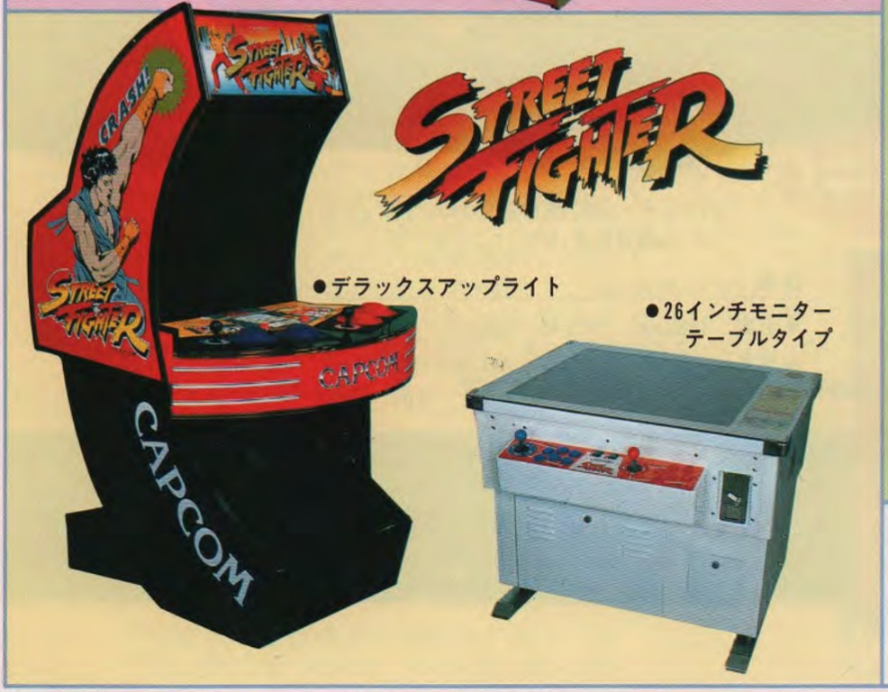 Advertisements showcasing Japanese Street Fighter One arcade cabinets in both Deluxe and Cocktail configurations.
Advertised Japanese Street Fighter One arcade cabinets in Deluxe and Cocktail versions. Image courtesy of DonPanetta, highlighting the potential for diverse cabinet styles in different markets.
European territories further diversified the Street Fighter One cabinet landscape, with Electrocoin distributing several variations. While they offered a Deluxe cabinet mirroring the US and Japanese designs, Electrocoin also produced multiple versions of the six-button cabinet. One notable European variant, highlighted in a UKVAC forum thread, showcases the regional adaptations and customizations that emerged in arcade distribution.
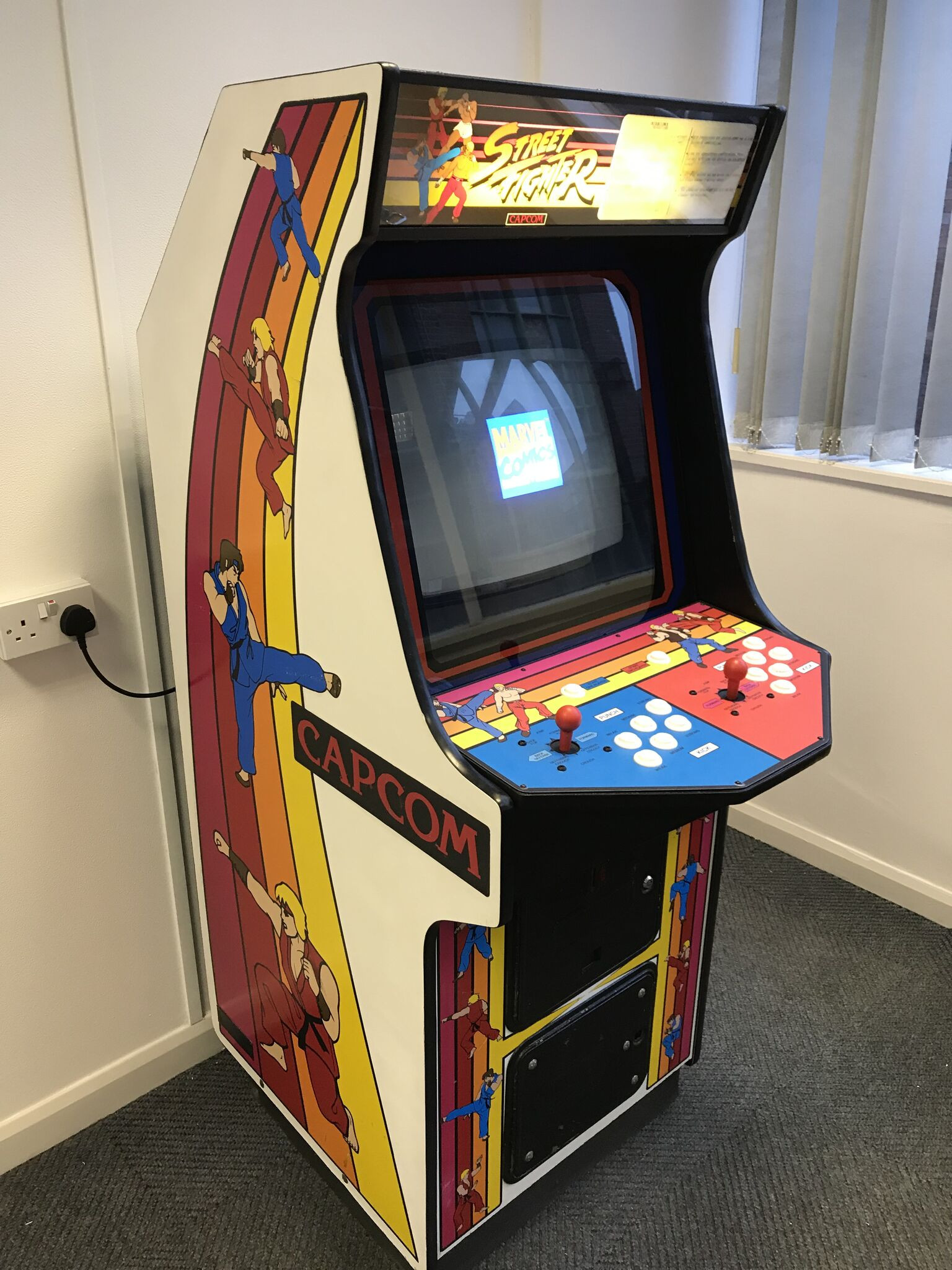 A European Street Fighter One cabinet distributed by Electrocoin, demonstrating regional variations in cabinet design.
A European Street Fighter One cabinet distributed by Electrocoin, exemplifying the diverse cabinet designs across different regions.
Sales Speculation and Cabinet Rarity
Pinpointing the exact number of Street Fighter One cabinets sold remains a challenge, as official sales figures are unavailable. Estimates often rely on interviews and anecdotal evidence, leading to a wide range of speculated numbers that may blend US and worldwide sales, and potentially include exaggerations. Sources cited by Polygon suggest that Deluxe pneumatic cabinets might have sold as few as 200 units, with more optimistic estimates reaching 1000, or even 3000. The dedicated six-button versions (Standard and/or Cocktail) are estimated to have sold in the region of 10,000, potentially reaching “tens of thousands.” One interviewee even speculated that up to 50,000 Street Fighter One PCBs (Printed Circuit Boards) were sold globally, encompassing both official and bootleg units.
These figures should be treated with caution, representing educated guesses rather than definitive data. For context, Street Fighter II: World Warrior, a conversion kit rather than a dedicated cabinet, is estimated to have sold around 60,000 “machines.” However, the ambiguity of “machines” and “conversion kits” makes direct comparisons difficult. Regardless of the precise numbers, it’s clear that Street Fighter One cabinets, particularly the pneumatic Deluxe versions, are relatively rare, making them highly sought-after collector’s items today.
Decoding the Main PCB: The Brains of the Operation
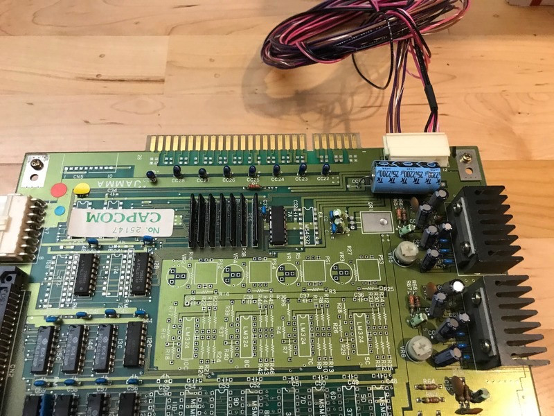
At the heart of the Street Fighter One arcade experience lies the Main PCB (Printed Circuit Board). This isn’t a single board, but a stack of three interconnected boards, designated A, B, and C, from top to bottom. This stacking configuration, while perhaps counterintuitive compared to later Capcom CPS1 and CPS2 boards where the A-board is at the bottom, maintains a consistent Capcom design element: the JAMMA (Japanese Arcade Machine Manufacturers Association) connector is always located on the A-board.
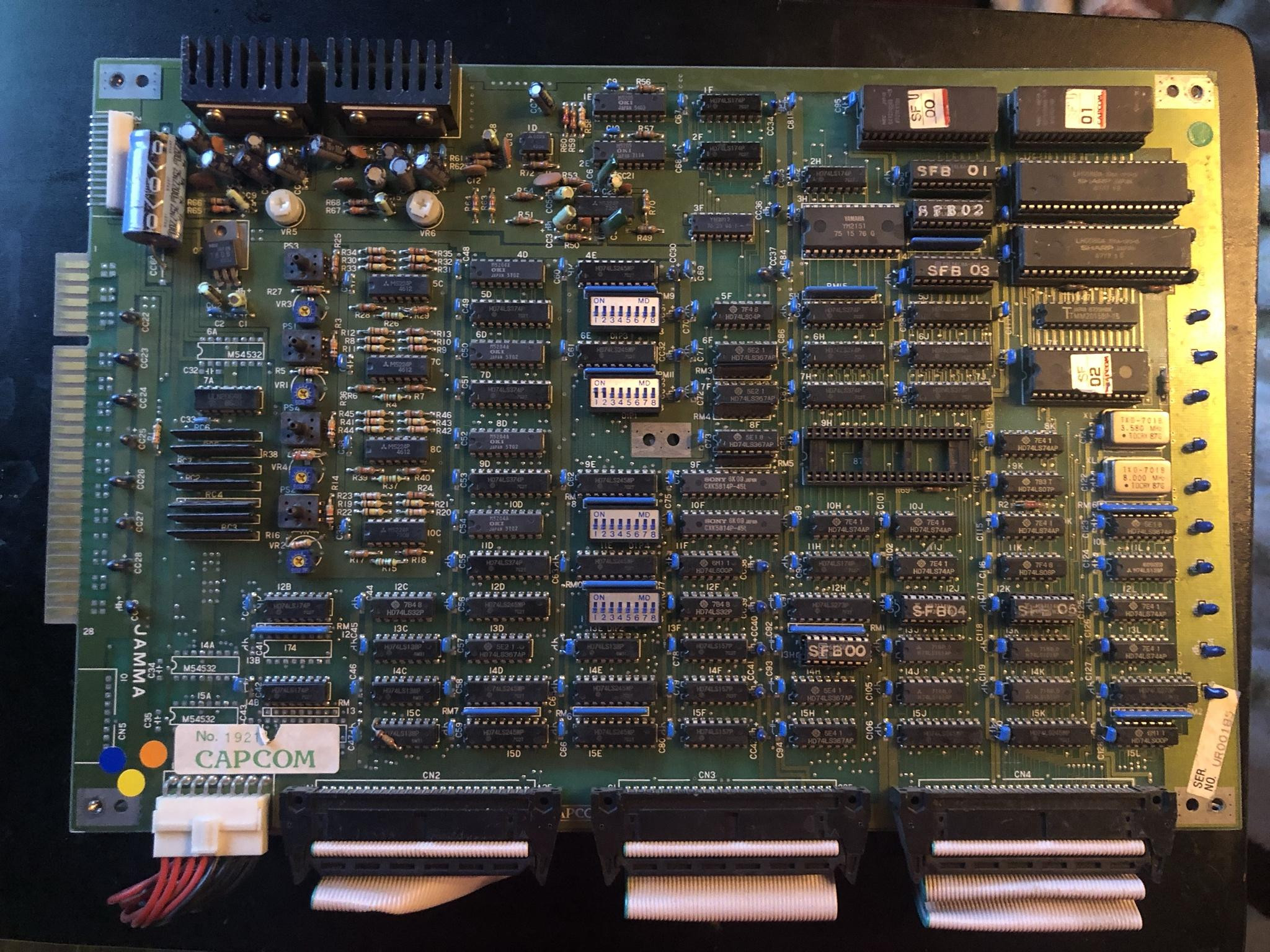 The Street Fighter One Pneumatic Main PCB, showcasing the three-board stack.
The Street Fighter One Pneumatic PCB, illustrating the three-board structure and component layout.
Through hands-on experience and board acquisition, it’s been observed that there are two primary versions of the SF1 PCB stack. Stacks labeled 87120-X (where X is A, B, or C) are designed exclusively for the six-button control scheme in their unmodified state. Conversely, PCB stacks labeled 86116-X-2 are versatile, capable of supporting both six-button and pneumatic controls. Many 86116 boards were converted from pneumatic to six-button configurations via a ROM (Read-Only Memory) swap. Intriguingly, some factory-distributed 6-button conversion 86116 boards, dubbed “Mark II” or “Neutered PCB” by Biomech011, arrived without the pneumatic hose connectors physically installed.
 The "Mark II" or "Neutered PCB," an 86116 board stack lacking pneumatic connectors.
The Mark II, or Neutered PCB as termed by Biomech011, an 86116 board variant without pneumatic connectors, designed for six-button configurations.
The 87120 board stack technically adheres to the JAMMA+ standard, akin to MVS (Multi Video System) or CHAMMA (Chinese JAMMA), due to the placement of buttons 4 and 5 for Players 1 and 2 at pins 25/c and 26/d, respectively. The 87120 A-board further includes three pins at connector CN5 for a sixth button for both players. Additionally, it boasts a four-pin connector (CN6) allowing for stereo sound output, a feature ahead of its time for many arcade games of the era.
When configured for six buttons, the 86116 pneumatic board stack becomes functionally similar to the 87120 set, but with subtle differences. Instead of dedicated connectors, the 86116 utilizes a single connector (CN6) for both stereo sound and buttons 3 and 6 for both players.
Physically separating the A, B, and C boards is straightforward. Removing the four screws at the corners of the A-board and the four PCB feet on the bottom of the C-board allows for easy disassembly.
While the B-boards from both 86116 and 87120 sets appear nearly identical, the A and C boards exhibit significant differences. Notably, the 86116 C-boards feature two daughtercards labeled 86116-E-X, similar to those found in Capcom’s 1943 and presumably other Capcom titles from that period. These daughtercards are absent in the 87120 C-boards.
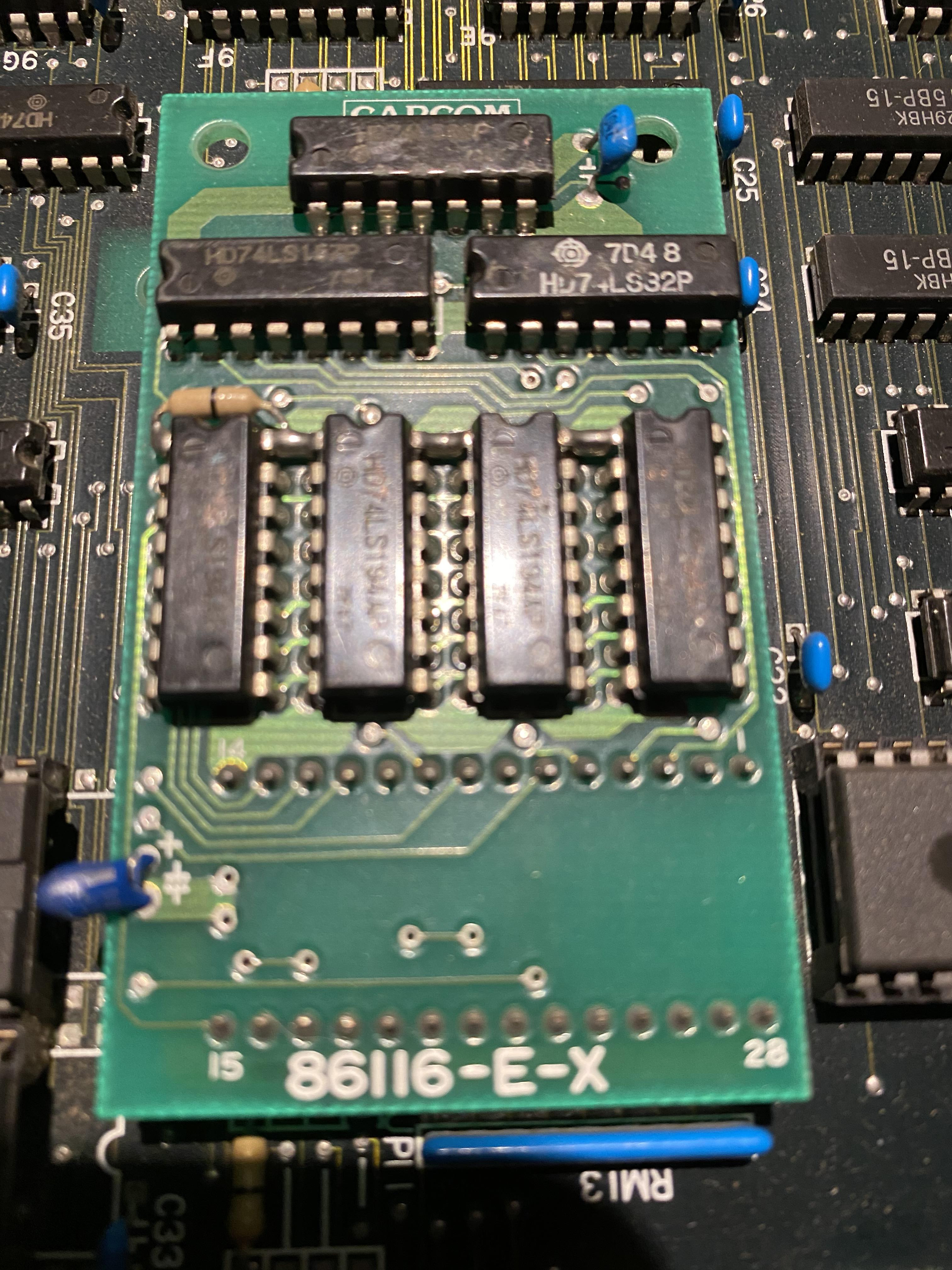 A daughtercard found on the 86116 C-Board, illustrating the modular design elements.
A daughtercard component on the 86116 C-Board, highlighting the modularity of the PCB design.
Interestingly, boards from both 86116 and 87120 stacks can be physically interchanged. However, simply mixing and matching boards from different sets results in an incompatible system that will not run the game. While the game might boot with swapped B-boards, it quickly crashes, as observed in testing various three-board combinations. Modifying the boards for cross-compatibility may be possible, but it falls outside the scope of this discussion and the expertise of this author.
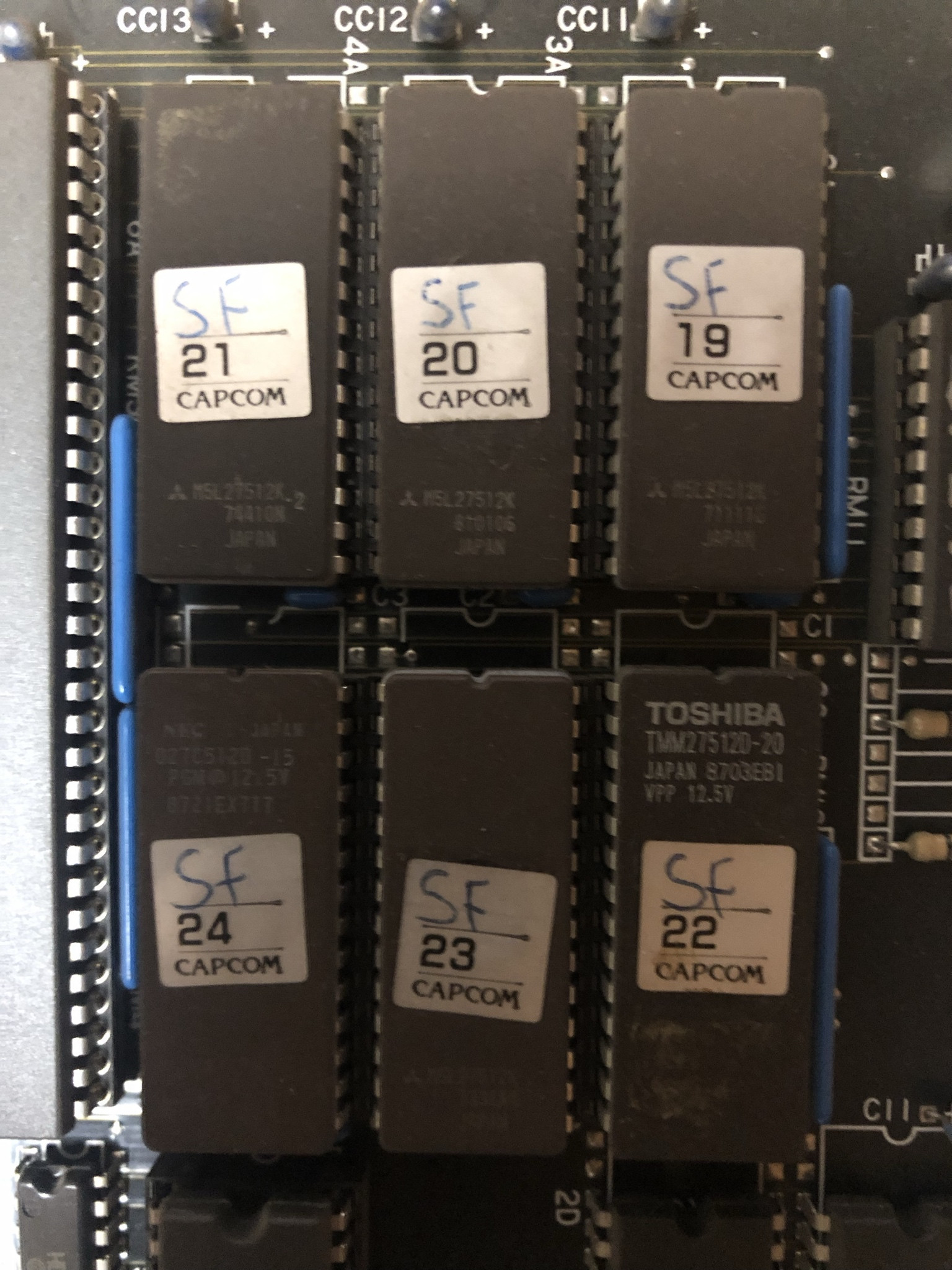 Street Fighter One CPU ROMs located on the C-Board, showcasing hand-written labels.
Street Fighter One CPU ROMs on the C-Board, featuring handwritten labels and providing insight into software storage.
Located on the C-board are the game’s ROM chips, specifically chips 19 through 24. These chips, originally 27c512 labeled, contain the core game data. The ROM file for the Street Fighter One Pneumatic version is commonly known as “Street Fighter (World, Analog buttons)” and is often found online under the filename “SF1.zip.”
The End PCB: An Unexpected Atari Connection
The End PCB in the Street Fighter One pneumatic cabinet is an electronic board, devoid of any pneumatic hose interfaces. Its primary function is to provide connections for power, video, sound, coin mechanisms, and controls for Players 1 and 2. Connectors on the End PCB are detailed in Sections 3-6 and 4-24 of the SF1 arcade manual.
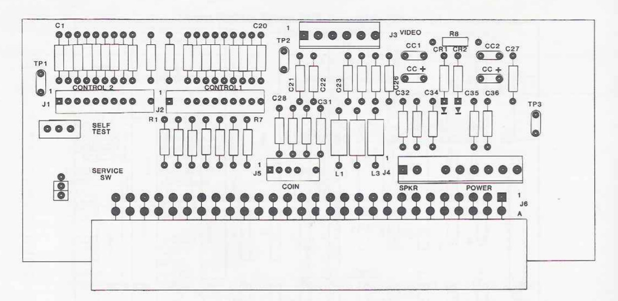 Schematic of the Street Fighter One End PCB, outlining its connections and components.
Schematic diagram of the End PCB, illustrating its electronic interfaces for power, video, audio, and controls.
Notably, the connectors for Player 1 and Player 2 buttons 5 and/or 6 are located on the Main PCB, not the End PCB. The 56-pin connector on the End PCB adheres strictly to the JAMMA standard, providing connections for only three action buttons per player. It lacks the traces for pins 25/c and 26/d, which are necessary for buttons 4 and 5. Consequently, the End PCB is inherently incompatible with a six-button PCB without modification. Despite this limitation, some End PCBs have been observed with modifications to enable pins 25/c and 26/d functionality.
An intriguing discovery, pointed out by Jamesv833, is the striking similarity between the Street Fighter One End PCB and the End PCB found in Atari’s Rolling Thunder. The Rolling Thunder manual confirms that the End PCBs are visually identical and share the part number A044201-01. Given that Rolling Thunder was released in 1986, preceding Street Fighter One’s 1987 debut, it’s highly probable that Atari repurposed their existing End PCB design for Capcom’s game. This reuse might explain why the SF1 End PCB was wired for action buttons 1-3 for both players, even though these buttons were not utilized in the pneumatic cabinet configuration.
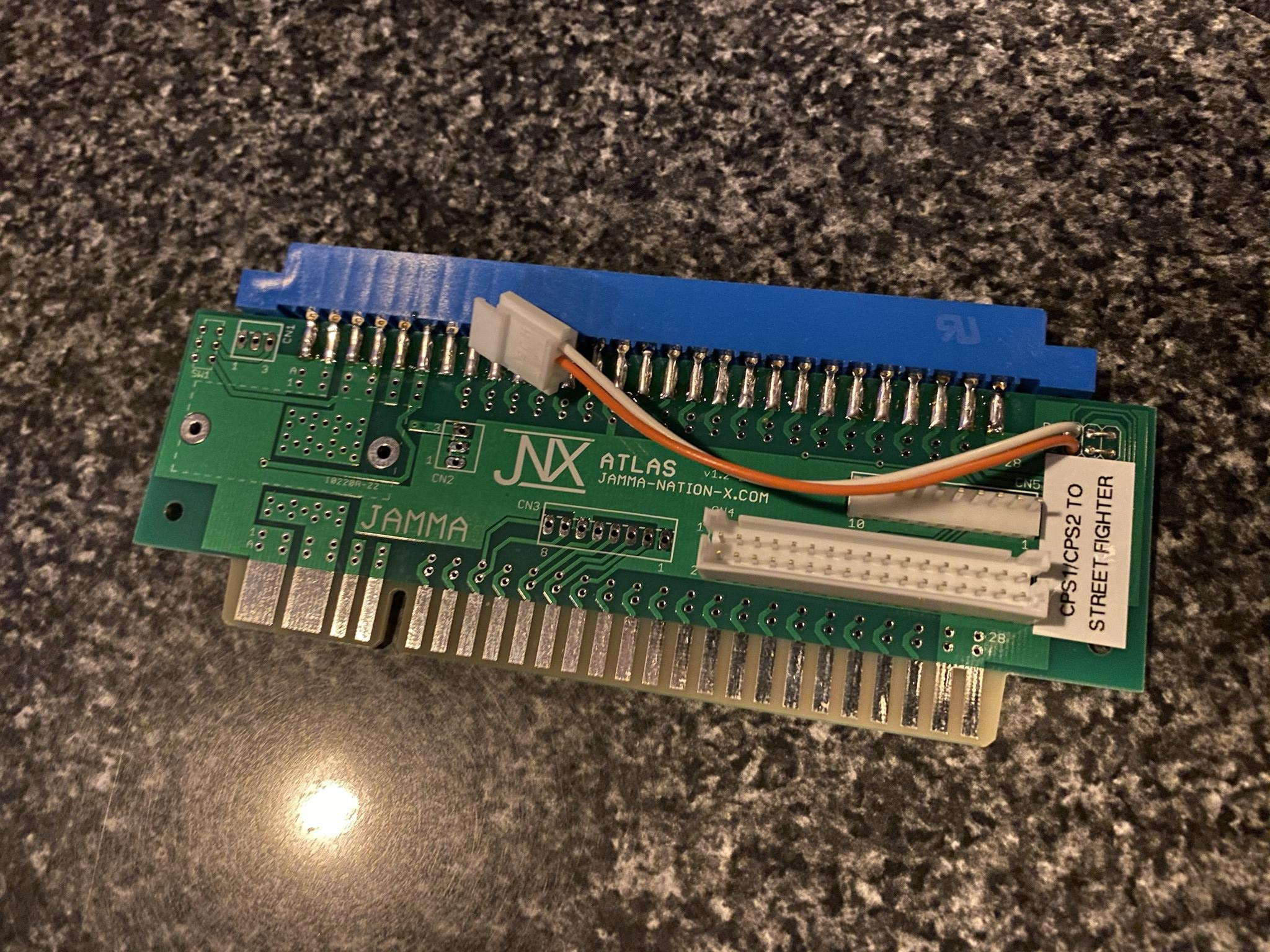 A more modern and functional End PCB replacement for Street Fighter One.
A modern replacement End PCB, offering enhanced functionality and compatibility for Street Fighter One cabinets.
Jamma Nation X offers a modern replacement End PCB for the six-button version of Street Fighter One. This replacement board is compatible with CPS (Capcom Play System) kick harnesses and requires different configurations depending on whether you are using an 86116 or 87120 SF1 board stack. Interestingly, the pinout of the 87120 board stack bears a strong resemblance to that of Street Fighter: The Movie: The Game, highlighting potential commonalities in Capcom’s arcade hardware designs.
The Junction Box: Directing the Airflow
The Junction Box is a distinctive U-shaped metal component mounted within the cabinet, playing a crucial role in the pneumatic control system. Identified by round colored stickers and the stamped marking “SFP-20,” the Junction Box houses a solid metal brick at its core. Each face of this brick features four holes drilled straight through, creating channels for airflow. These holes are terminated at each end by barbed tube connectors, also constructed from metal.
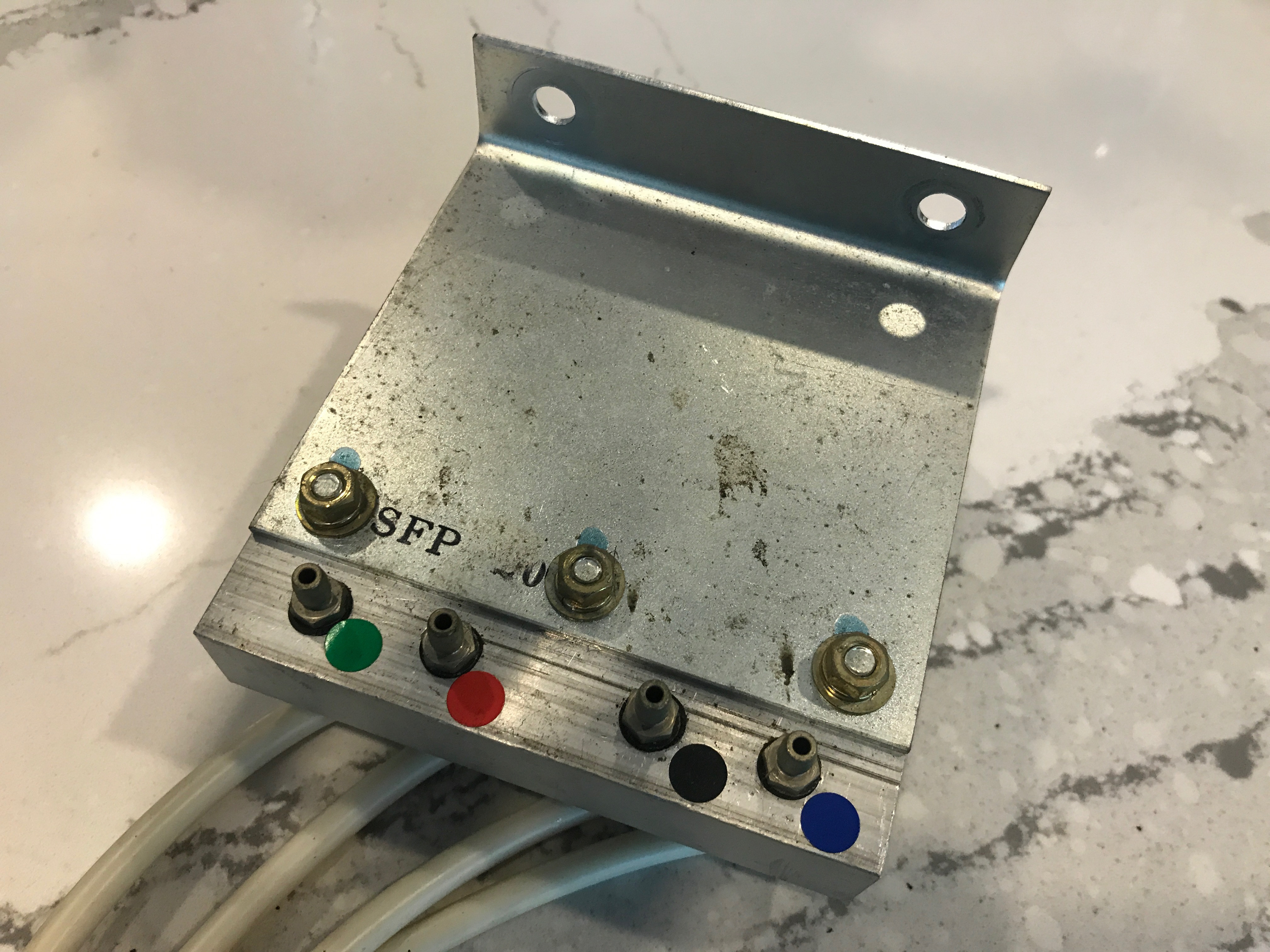 Close-up view of the Junction Box, showing its construction and pneumatic connectors.
A detailed close-up of the Junction Box, highlighting its metal construction, colored stickers, and pneumatic tube connectors.
According to the Street Fighter One instruction manual (Section 3-5), the pneumatic controls utilize “silicon tubes.” These tubes, in a sample set, came in two lengths: 11.75″ and 23.75″. While either length can be used on either side of the Junction Box, longer tubes are often preferred on the Control Panel end to facilitate easier installation and removal. The tubes have an outer diameter of 0.25″ and an inner diameter of 0.125″. Alternative fuel line tubing, available in colors like red, can also be used as a functional and visually distinct substitute.
The pneumatic connectors are color-coded on both the Pneumatic PCB and the Junction Box to ensure consistent and correct installation. Player 1 Punch and Kick are associated with Blue and Black dots, respectively, while Player 2 Punch and Kick correspond to Red and Green dots. It’s important to note that these color designations are arbitrary and can be interchanged without affecting functionality.
Pneumatic Control Panels: Inside the Bash Pads
The pneumatic control panels are topped with a robust 1/4″ thick black rubberized metal plate. This plate features openings for the joystick and two pneumatic cylinders, the latter capped by rubber buttons, officially termed “bash pads,” and additional black rubber padding.
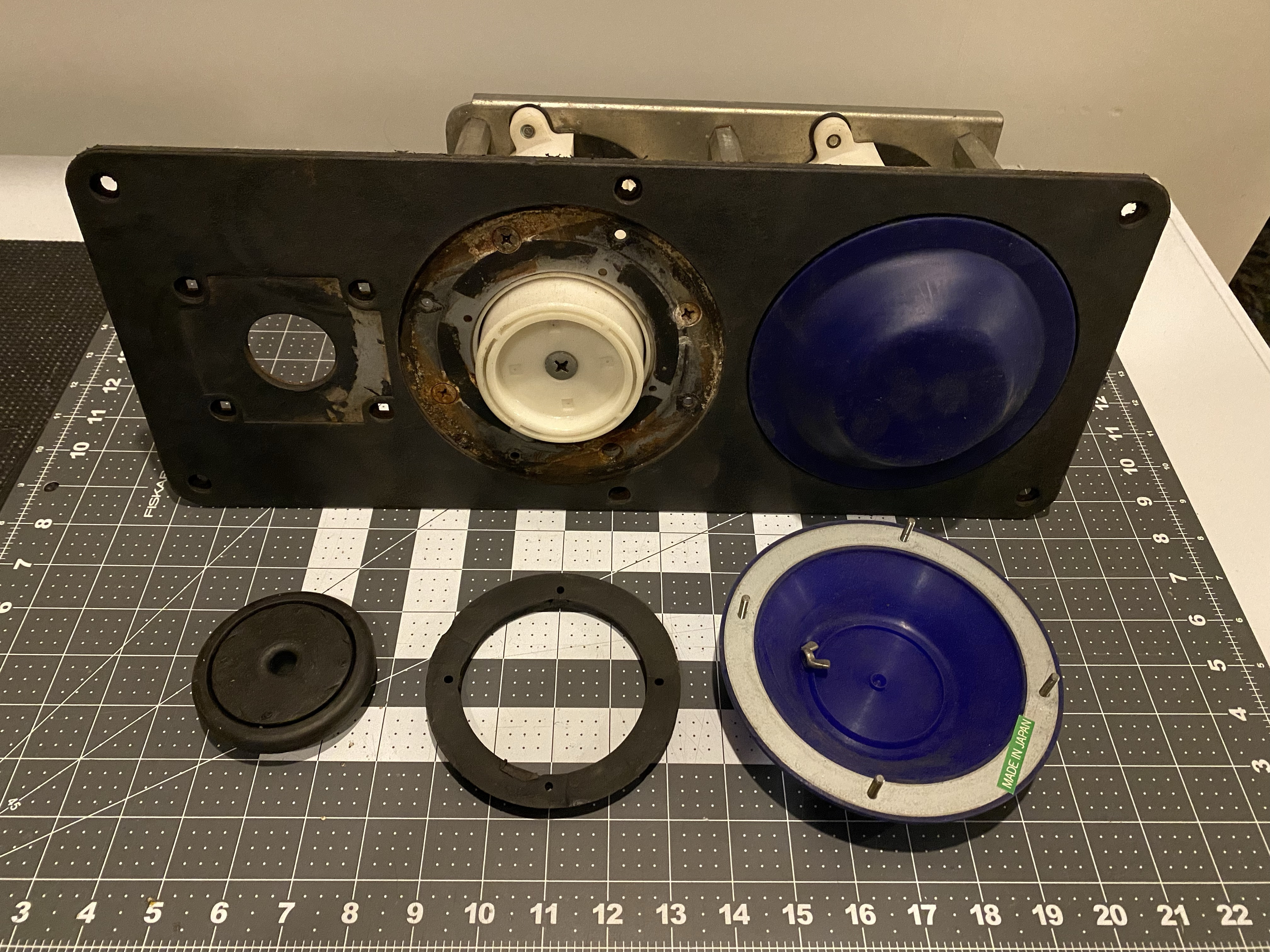 A pneumatic control panel with a bash pad removed, revealing the white pneumatic cylinder.
A Street Fighter One pneumatic control panel with a bash pad removed, exposing the white pneumatic cylinder and internal components.
Each white cylinder is constructed from thick plastic and features a mobile and compressible top section (often streaked black). When compressed, air is expelled from the tube connector at the cylinder’s base. A visible spring coil near the base provides resistance and recoil when the cylinder top is depressed, creating the tactile feedback of the pneumatic controls.
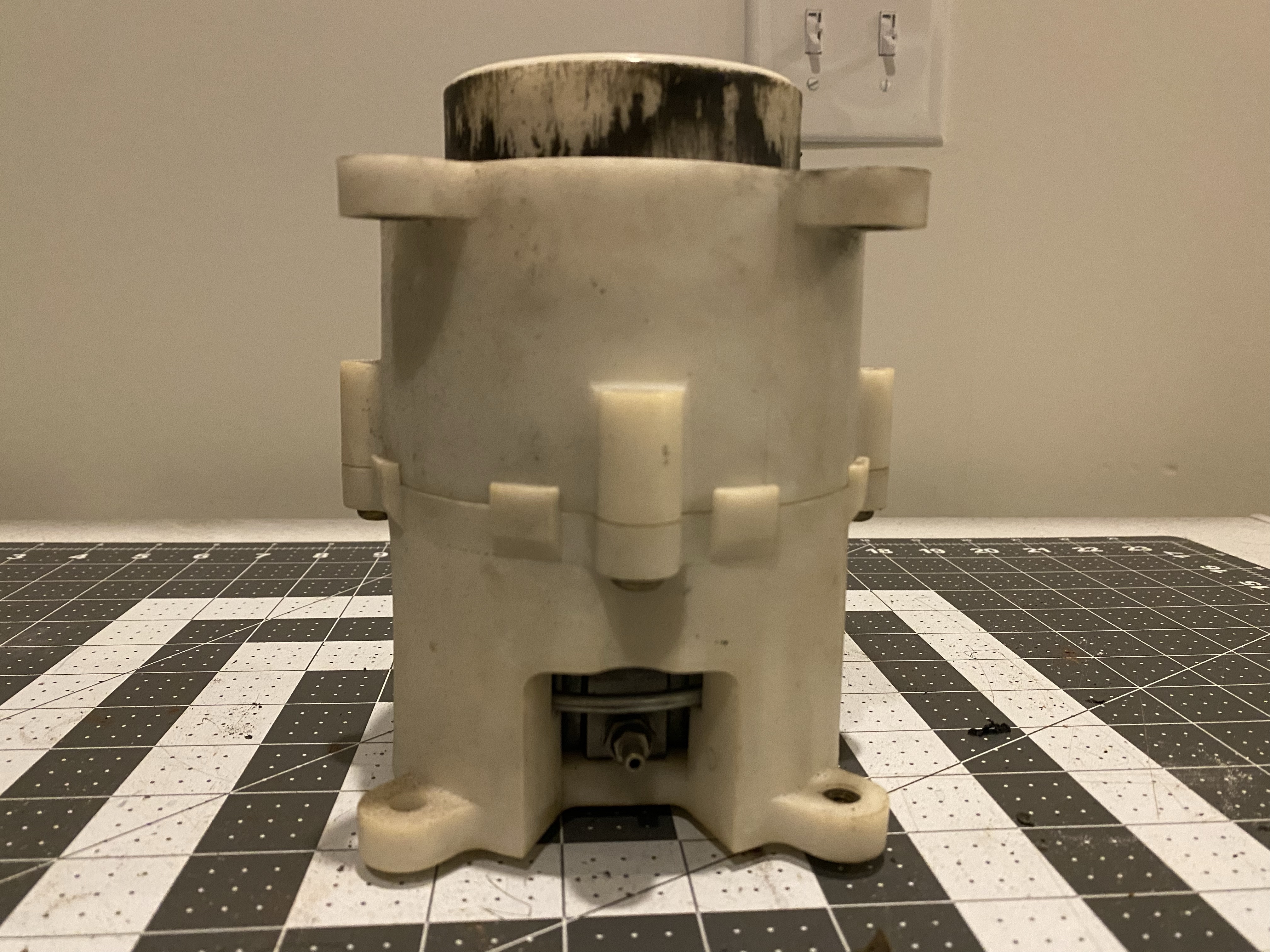 A close-up view of the pneumatic cylinder, highlighting its construction and components.
A detailed view of the pneumatic cylinder, emphasizing its plastic construction and the mobile top section.
The white cylinder is held together by four large screws around its center. Inside, it houses a spring and a pneumatic piston.
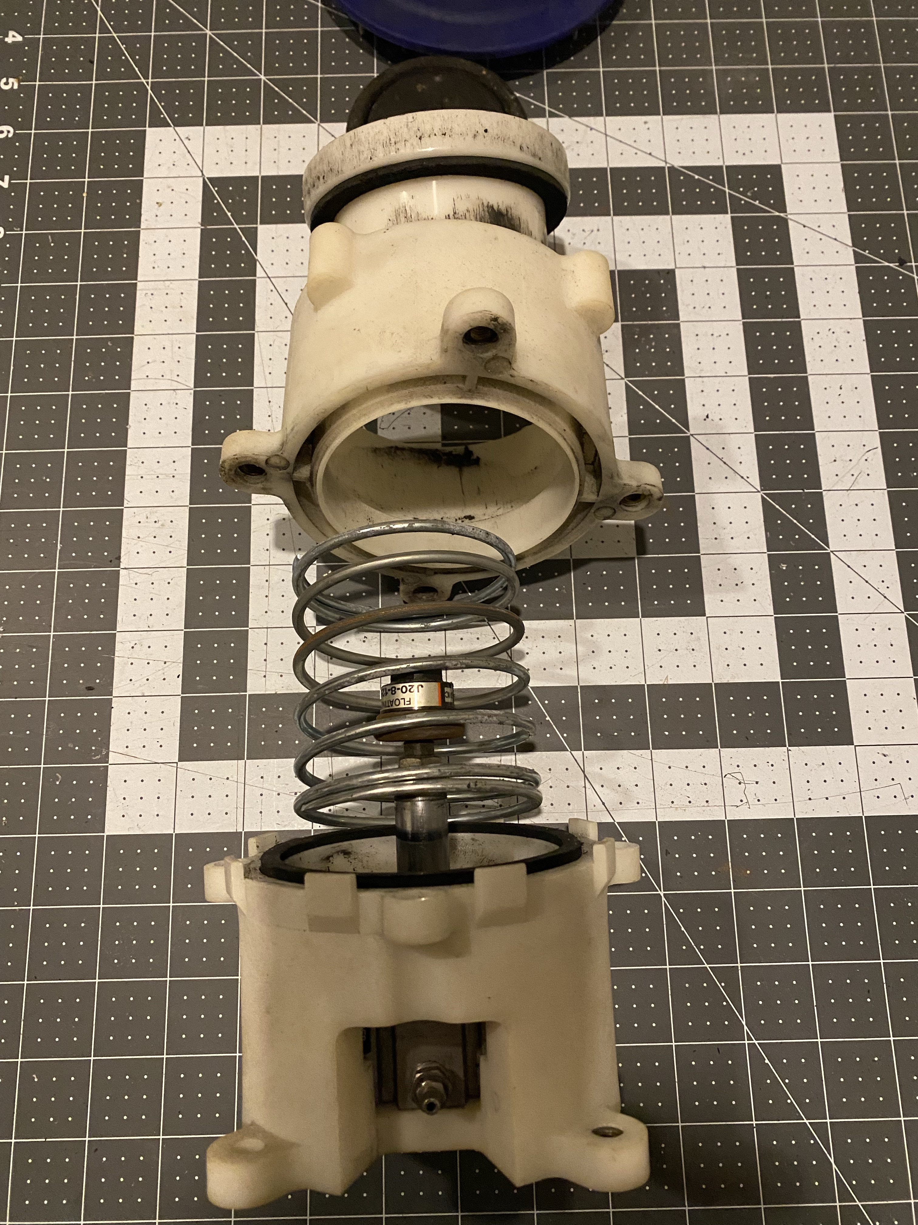 An exploded view of the pneumatic cylinder, showcasing its internal components.
An exploded diagram of the pneumatic cylinder, illustrating the internal spring, piston, and seals.
These pneumatic pistons within the Control Panel cylinders are still manufactured by SMC Pneumatics (Yorba Linda, CA). The complete pneumatic piston assembly (Part number: CQ2B32-01-56670) was custom-made for Atari/Capcom and is no longer available as a complete unit. However, SMC representatives indicate that the configuration could be reproduced if the correct measurements are obtained and compared to their current standard catalog dimensions. Knowledge of piston “stroke” terminology could be valuable in recreating these pneumatic controls.
 Animated representation of the pneumatic cylinder and piston, showcasing its mobile floating joint.
Animated depiction of the pneumatic cylinder and piston in action, highlighting the mobile floating joint and air compression.
The pneumatics produce a distinctive, somewhat pleasing sound during gameplay. SMC Pneumatics still manufactures the floating joints (Part number: JA20-8-125) and seal repair kits (Part Number: CQ2B32-PS) for these pneumatic pistons. While the industrial-grade floating joints are unlikely to fail under normal use, the seal repair kits are practical for refurbishing pneumatic controls experiencing inconsistent performance.
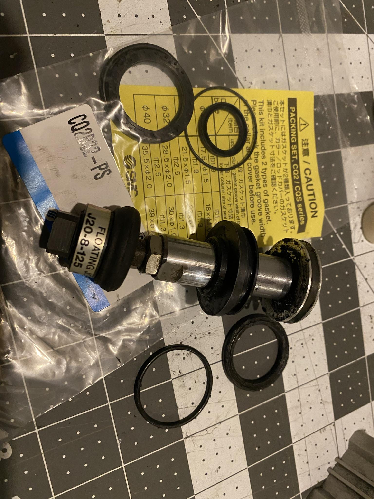 The pneumatic piston and O-rings in need of refurbishment, demonstrating potential wear points.
A pneumatic piston and its O-rings showing signs of wear and tear, highlighting the need for refurbishment in vintage systems.
For a more comprehensive visual exploration of the pneumatic controls and their components, a detailed gallery is available, offering valuable pictures for disassembly, reproduction attempts, or simply understanding the inner workings of this unique arcade control system.
Conclusion: Resurrecting the Pneumatic Legacy
The pneumatic cabinet of Street Fighter One represents a fascinating, albeit commercially less successful, chapter in arcade gaming history. Its complex system of PCBs, junction boxes, and pneumatic cylinders showcases the innovative engineering of the era, even if it ultimately gave way to more conventional control schemes. Understanding the technical intricacies of the Street Fighter One pneumatic cabinet not only deepens our appreciation for this pioneering game but also provides valuable insights into the evolution of arcade technology.
References